logo

Internal Combustion Engines

  • No Rating
  • (0 Reviews)
  • 4 User Enrolled

Internal Combustion Engines

Internal Combustion Engines are heat engines in which combustion takes place inside of engine cylinder with an oxidizer (generally air). Internal combustion heat engines work on the principle of the ideal gas law:

  • No Rating
  • (0 Reviews)
  • 4 User Enrolled
  • Free
10-Day Money-Back Guarantee


Course Content

9 sections • 13 lectures • 02h 10m total length
IC Engine Basics

Internal Combustion Engines are heat engines in which combustion takes place inside of engine cylinder with an oxidizer (generally air). Internal combustion heat engines work on the principle of the ideal gas law: 

pV=nRT. (Ideal gas law)

An internal combustion engine has a chamber, which has fuel added to it which ignites in order to raise the temperature of the gas.When heat is added to the system, it forces gas inside to expand, this causes the piston to rise, and in case of  a gas turbine, the hot air is forced into the turbine chamber...By attaching the piston or turbine to a camshaft, the engine is able to convert a portion of the energy input to the system into useful work.To compress the piston in an intermittent combustion engine, the engine exhausts the gas. A heat sink is then used to keep the system running at a consistent temperature. A gas turbine, which uses continuous combustion, simply exhausts its gas continuously rather than in a cycle.

preview 10min
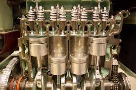
cylinder,cylinder head,piston,piston rings,connecting rod,crankshaft & other major components

What are the components which makes an IC engine.... The answer is hundreds of. Out of these many components, we are going to have a discussion regarding cylinder,cylinder head,piston,piston rings,connecting rod,crankshaft & other major components.A brief description about each of these major components are enlisted below ;

Cylinder - Cylinder is the main body of IC engine. Cylinder is a part in which the intake of fuel, compression of fuel and burning of fuel take place. The main function of cylinder is to guide the piston.

Cylinder head - One end of the cylinder is closed by means of cylinder head. This consists of inlet valve for admitting air fuel mixture and exhaust valve for removing the products of combustion.The inlet valve, exhaust valve, spark plug, injector etc. are bolted on the cylinder head. The main function of cylinder head is to seal the cylinder block and not to permit entry and exit of gases on cover head valve engine.Generally made up of aluminium alloys.

Piston -  It transmits the energy to crankshaft through connecting rod.

Piston rings - These are used to maintain a pressure tight seal between the piston and cylinder walls and also it transfer the heat from the piston head to cylinder walls.These rings are fitted in grooves which have been cut in the piston. They are split at one end so they can expand or slipped over the end of piston.Generally made of highly elastic material or fine grain cast iron.

Connecting Rods - One end of the connecting rod is connected to piston through piston pin while the other is connected to crank through crank pin.It transmits the reciprocatory motion of piston to rotary crank."Big end of the connecting rod is connected to the crankshaft and the small end is connected to the piston by using piston pin".Generally made of low carbon steels.

Crank - A lever between connecting rod and crank shaft.

Crank Shaft The function of crank shaft is to transform reciprocating motion in to a rotary motion.The crankshaft of an internal combustion engine receives the efforts or thrust supplied by piston to the connecting rod and converts the reciprocating motion of piston into rotary motion of crankshaft.The crankshaft mounts in bearing so it can rotate freely."The shape and size of crankshaft depends on the number and arrangement of cylinders." 


preview 15min
opening and closing of the intake and exhaust valve

A valve timing diagram is a graphical representation of the opening and closing of the inlet (Intake) and outlet (Exhaust)  valve of the engine, The opening and closing of the valves of the engine depend upon the movement of piston from TDC (Top Dead Center) to BDC (Bottom Dead Center). Encapsulating the crank revolution corresponding to the relevant movement of the piston, valve timing diagrams are made.

The valve timing diagram comprises of a  360 degree figure which represents the movement of the piston from TDC to BDC in all the strokes of the engine cycle, Which is measured in degrees and the opening and closing of the valves is controlled according to these degrees. 

What is the need for Valve Timing Diagram ?

A normal engine works such that it completes approximately 1,00,000+ cycles per minute. Hence it is mandatory to monitor & supervise a system which can enable :-

  • Providing engine with a mixer of air and fuel or simply pure air in case of diesel engine when required ( at the time of suction) which is the necessity of the engine.

  • Complete seizure of the combustion chamber at the instant at which the combustion of air-fuel mixture takes place as the leakage can cause damage to the engine and can be hazardous as well.

  • Synchronization between  the steps of a cycle of the engine from intake of air-fuel ratio to the exhaust of combustion residual (Burnt gases).

  • Ideal timing for the opening and closing of the inlet and outlet valve which in turn protect the engine from defects like knocking or detonation.

  • A high compression ratio required to ignite the fuel especially in case of diesel engine by overlapping the closing of the valve (Valve overlapping).

  • The study of the details of the combustion that is required for the modification of the power of the engine.

  • The cleaning of engine cylinder which in turn maintain the quality of combustion and decreases wear and tear inside the cylinder.

Hence for these many reasons, engines (whether they are 2 or 4 stroke) are designed keeping valve timing diagram meticulous & accordingly. So that the movement of piston from TDC to BDC is provided with the ideal timing of opening and closing of the intake and exhaust valves respectively.

This lecture covers the basics of making & understanding the theoretical valve timing diagram of two & four stroke cycle internal combustion engines

preview 10min
Suction, Compression, Expansion & Exhaust

Each stroke in IC engines forms a sequence of operations in one cycle of an IC Engines i.e suction stroke, compression stroke, expansion stroke, and exhaust stroke.

When an engine is working continuously, we can consider a cycle starting from any stroke. We know that when the engine returns back to the stroke where it started, we say that one cycle has completed. The following sequence of operation in a cycle is widely used.

  1. Suction stroke :- In this stroke, the fuel vapor in correct proportion, is supplied to the engine cylinder.


  2. Compression stroke :- In this stroke, the fuel vapor is compressed in the engine cylinder.


  3. Expansion or working stroke :- In this stroke, the fuel vapor is fired just before the compression is complete. It results in the sudden rise of pressure, due to expansion of the combustion products in the engine cylinder. This sudden rise of pressure pushes the piston with a great force and rotates the crankshaft. The crankshaft, in turn, drives the machine connected to it.


  4. Exhaust stroke :- In this stroke, the burnt gases (or combustion products) are exhausted from the engine cylinder, so as to make space available for the fresh fuel vapor.

preview 5min
Scavenging process

During the end of exhaust stroke, certain residual of burnt gases still remains in the combustion chamber. Scavenging is that process by which these remnants can be removed out of the engine cylinder prior to suction stroke of next cycle.

preview 10min
method

Different Methords

preview 5min
Process

Process

preview 10min
explosive detonation

Detonation is when part of the unburned /partially burned fuel air mixture reaches a critical pressure and temperature and transitions from a normal burning process to an explosive detonation that progresses at near the speed of sound. 

preview 10min
generates a spark or heats

An ignition system generates a spark or heats an electrode to a high temperature to ignite a fuel-air mixture in spark ignition internal combustion engines.. In this lecture we are briefly discussing about the two types of ignition system in IC engines. Coil & Magneto ignition. 

  • Coil Ignition Systems

These ignition systems consist of a 6 or 12-volt battery, resistance, ignition switch, ammeter.It also consists high tension coil, contact breaker, condenser, high tension distributor and spark plug.The high tension coil consists of a waterproof casing containing a few turns of heavy wire forming a primary winding.

It is surrounded by about 20000 turns of fine wire forming a secondary winding.Both windings being wound over a laminated soft iron core and insulated from each other.One end of the secondary winding is earthed. While the other end connected through a heavily insulated wire into the center of the distributor cap.A carbon contact carries the current to the rotor arm.This is made of bronze which revolves and distributes the current to the various cylinders through spark plug leads

  • Magneto Ignition Systems

This system consists of a switch, a magneto, contact breaker, condenser, high tension distributor and spark plugs.The magneto consists of a fixed armature having a primary and secondary winding.It has also a rotating magnetic assembly driven from the engine.The electromotive force induced in the secondary is insufficient to produce a spark.Consequently, it is transformed into the high voltage by the contact breaker in the primary circuit.

preview 20min
Battery And Coil Ignition System.

Battery And Coil Ignition System.I explained Following topic 1. Construction of Battery And Coil Ignition System 2. Working of Battery And Coil Ignition System

preview 10min
Magneto Ignition Systems


This system consists of a switch, a magneto, contact breaker, condenser, high tension distributor and spark plugs.The magneto consists of a fixed armature having a primary and secondary winding.It has also a rotating magnetic assembly driven from the engine.The electromotive force induced in the secondary is insufficient to produce a spark.Consequently, it is transformed into the high voltage by the contact breaker in the primary circuit.

preview 10min
deliver fuel into the engine

The purpose of the fuel injection system is to deliver fuel into the engine cylinders, while precisely controlling the injection timing, fuel atomization, and other parameters. The main types of injection systems include pump-line-nozzle, unit injector, and common rail. Modern injection systems reach very high injection pressures, and utilize sophisticated electronic control methods. 

preview 10min
cooling Engine

All internal combustion engines are equipped with some  type  of  cooling  system because  of  the  high temperatures  they  generate  during  operation.The temperature in the combustion chamber during the burning of fuel is much higher than the melting point of iron.Therefore, if nothing is available to cool the engine during operation, valves burn and warp, lubricating oil breaks  down,  and  bearings  and  pistons overheat resulting in engine seizure. At the same time, the engine must not be allowed to run too cold. An engine running cold does not burn all the fuel taken into the combustion chamber,  causing  carbon  deposits  to  form  that  reduce fuel  mileage,increase wear and reduce engine  power.

preview 5min

Requirements

  • Nill

Description

An internal combustion engine is a heat engine in which the combustion of a fuel occurs with an oxidizer in a combustion chamber that is an integral part of the working fluid flow circuit.

Recently Added Courses

blog
Last Updated 13th June 2025
  • 6
  • Free
blog
Last Updated 13th June 2025
  • 0
  • Free
blog
Last Updated 28th May 2025
  • 2
  • Free
blog
Last Updated 28th May 2025
  • 0
  • 19.00₹
  • 100.00₹

About the Instructor

instructor
About the Instructor

Creative Knowledge From Various Good Teachers From Various Locations. Knowledge is Free Always